Restoring & Modifying 1971 OIF TR120

Triumph Motorcycle Forum - TriumphTalk

Help Support Triumph Motorcycle Forum:

This site may earn a commission from merchant affiliate links, including eBay, Amazon, and others.
I have two carburetor-related questions. The second will be in the following post:

First - I was reading the shop manual together with the Amal carburetor tuning guide to anticipate getting the mixture right for my typical operating elevation range of 5,000 to 6,000 ft.

This is critical because the guide suggests that at my elevation I can expect up to a 20% loss of power if the engine's overly rich--that's a lot of power! And as much as a 30% loss at 9,000 ft., which is the elevation of my neighbors' cabin among the Ponderosa pines in the Jemez Mountains.

Also: I see that key to getting the mixture right is understanding that, from 1/4 to 3/4 slide opening (or throttle valve position), it's the degree of throttle valve cutaway that controls the mixture.

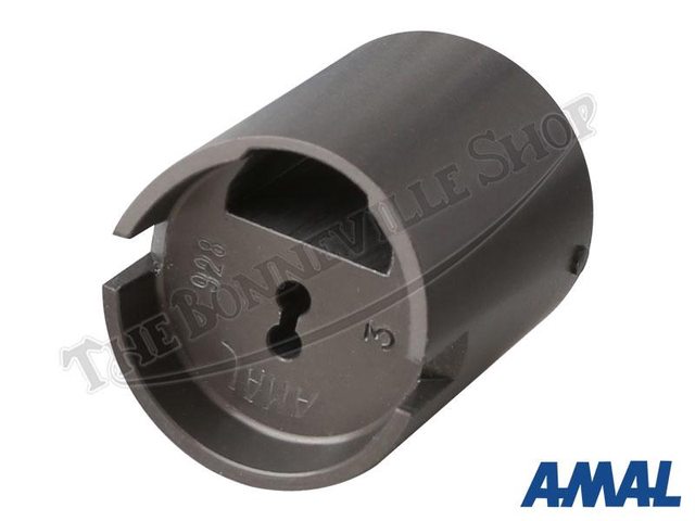
I bought the bike fitted with (brand new) Amal Mk I Concentric 900 Series 30mm carbs. They have the aluminum hard anodized slides, but when resolving the actuation of the throttle and choke cables, I did not know to look for the cutaway markings on the throttle valve(s). I see that they come in 2.5, 3, 3.5 and 4 cutaways.

When I get a moment, I'll pull the top on one of the carbs to see which came with the new set of carbs--but does anyone know where to look for the cutaway designation? I don't mind buying valves with cutaways one size smaller and larger than what I've got--especially as I'm anticipating installing Dunstall replicas at some point, and plan to do some over-the-road touring on this bike (especially if I can meet some vintage bike owners who might ride along as I pass through their states).

However, it would be helpful to me if anyone has experience tuning an internally stock Unit 650 in my altitude range, and might know which cutaway netted the ideal mixture.
 
Second batch of carb-related questions:

I cleaned up the manifolds, and also bought the phenolic spacers seen in the first photo. I live in New Mexico, where 90~100 F. is routine during summer, so imagined these might help avoid vapor lock after the bike sits for a spell following a highway run.

I couldn't find longer studs to fit these spacers--and am not sure how to R&R the OEM studs on the manifolds. Any suggestions?

I have also seen this style of finned aluminum spacer. They look neat but I wonder if anyone has experience with both types and could tell me which is more effective at preventing conduction heating of the carb float chamber via the manifold?

Or, alternatively, is this an issue with these bikes?
It certainly is with my '51 FL Harley, but that has a slightly more circuitous intake tract than this straight-shot, shorty manifold.
 

Attachments

  • carb spacers.jpg
    carb spacers.jpg
    329.9 KB · Views: 26
View attachment 56843
bought the phenolic spacers
couldn't find longer studs
The phenolic insulating spacers were not fitted to 650 twins after 68, 69 onwards 650 (and later 750) have the same gap between carb and manifold filled with the special thick O ring as your bike.

Reason Triumph swapped the 650 twins to 69 onwards gap-'n'-O-ring was the previous carb mounting was solid, engine vibration frothed the fuel at high rpm, weakened the mixture, caused holed pistons ...

Pre 69 Bonneville carbs were bolted to the manifolds (with the phenolic spacers in between), the manifold looks the same as the one in your photo but almost certainly has a Cycle-derived thread (probably 26 tpi); otoh, your bike's manifold threads are more likely to be UNEF or UN Constant Pitch 28 tpi (but you might want to check?).

seen this style of finned aluminum spacer
They are made to fit the carb mounting studs Triumph used from part way through 72; if you want to see the later parts drawing and listing, https://partsbooks.britishonly.com/partsbooks/20-10201C.pdf, .pdf pages 34/35.

preventing conduction heating of the carb float chamber via the manifold
an issue with these bikes?
Ime, yes, even in the UK's lower ambient temperatures.
 
Life has been seriously intervening with my tinkering, and frankly has thrown me for quite a loop these last couple of months (deaths, divorces, and disasters, oh my!). But I'm back at it and preparing to R&R the headset bearings and races as they feel notchy. Also, just ordered new bushes and dust excluders for the swing arm--which I'm sure, based on the condition of the headset, need replacing, too. Got the bush-extraction/replacement tool, as it was amazingly cheap from a UK supplier.

The weather has been splendid lately here in the high desert, if quite chilly. But after I finish modifying the clutch cable on my '51 Harley FL--because I need something to ride to keep from going insane--and when the parts come in for these two bits, I'll dive into the primary & clutch inspection, alternator upgrade, install the tranny sprocket and new seal, fix the headset and swingarm, and fire her up.

I need to give her a go to decide whether I will indeed proceed with the front disc conversion imminently or stick with the OEM TLS front brake at least for the interim. I do not feel safe testing her out with the notchy headset--and of course would need different spokes to fit the aluminum rims discussed earlier, depending on which front brake hub I settle on.

Happy New Year to all of you.
If the OEM (Conical hub) TLS brake is operating correctly, it should be very good. Just make sure there is no corrosion on the pivots where they go through the brake plate.
 
The phenolic insulating spacers were not fitted to 650 twins after 68, 69 onwards 650 (and later 750) have the same gap between carb and manifold filled with the special thick O ring as your bike.

Reason Triumph swapped the 650 twins to 69 onwards gap-'n'-O-ring was the previous carb mounting was solid, engine vibration frothed the fuel at high rpm, weakened the mixture, caused holed pistons ...

Pre 69 Bonneville carbs were bolted to the manifolds (with the phenolic spacers in between), the manifold looks the same as the one in your photo but almost certainly has a Cycle-derived thread (probably 26 tpi); otoh, your bike's manifold threads are more likely to be UNEF or UN Constant Pitch 28 tpi (but you might want to check?).


They are made to fit the carb mounting studs Triumph used from part way through 72; if you want to see the later parts drawing and listing, https://partsbooks.britishonly.com/partsbooks/20-10201C.pdf, .pdf pages 34/35.


Ime, yes, even in the UK's lower ambient temperatures.

Thanks for the detailed info as always, Rudy. I've downloaded the parts replacement book for my files.

So, to be clear - are you suggesting that it's a good idea to install finned aluminum spacers, or did you simply mean to confirm that some effective method of preventing conduction is in order?

If so, do you favor the finned spacers, or is the thick O-ring-n-gap method just as good? Presumably, the finned spacers would transmit high-rpm vibration just as well as phenolic spacers. I currently have thin O-rings fitted, but obviously it's simple to swap them out for the thick ones.
 
If the OEM (Conical hub) TLS brake is operating correctly, it should be very good. Just make sure there is no corrosion on the pivots where they go through the brake plate.

Thanks for weighing in.

I've heard that from a handful of experienced people, and of course there are tons of others who insist that the OEM Conical hub TLS front brake is garbage. I must say that, though I've yet to have it on the road, after installing a new cable (sans brake switch) mine feels very sensitive--and I've yet to install the longer levers I had intended to try out before resorting to the DIY disc conversion.
 
slides are marked on the inside

h32qiWSl.jpg


the bigger the number, the taller the cutaway, and the leaner the slide.

i dont think you are going to be seeing very much of an effect from the throttle slide above about 1/4 throttle. the slide cutaway is mostly to smooth the transition between the idle curcuit and what is coming up the needle jet around the needle. mid-throttle is mostly the needle jet diameter and needle position.

elevation increase richens the mixture. you will initiallyy need to lower tbe needle to compensate, and possibly switch to a smaller needle jet, perhaps a 105, down from a 106, if tbats what you have. if you do install a smaller needle jet, your new needle position might be up or down from where it is now.

you will also need to decrease the size of the main jet.

doing all this will not recover the horsepower you lose from moving to a location with reduced air density, but it will recover the additional horsepower you would lose by not correcting the mixture for your new elevation.

testing the cutaway is easy with the engine on the stand. wsrm it up, let it idle, then smoothly open the throttle to about 1/2. if the engine stumbles and stalls, the slide is too lean. if it labours and burbles, its too rich. you want a smooth transition from the idle circuit to the main circuit.

in the white mountains in arizona at 10 000 feet, my un-corrected T120 would only go 45mph and the exhaust sounded like a hamster farting.
 
Last edited:
here is a very useful chart, showing th erelative effects of the different fuel circuits against the throttle opening. click on it to see the whole thing.

this chart was modelled after th emikuni VM factory chart, but it is NOT the same. on an amal carb, the needle lifts completely out of the needle jet at wide open throttle, so the main jet is 100 percent responsible for mixture up there. mikunis keep some of the needle in the needle jet at all times, so the needle clip position and needle taper has a slight effect even at full throttle.

look at the chart and you can see that the throttle slide is going to be most important at 1/8 to around 1/4- and a little above-- more or less filling in for the pilot circuit as it fades away. the real player in midrange is the needle jet diameter and needle clip position. once youre at 3/4 throttle, its all main jet.

i am not very knowledgable about amals, but iirc, the needle diameter is fixed and all you can mess with is needle jet and clip position.
 

Attachments

  • amal jetting chart.PNG
    amal jetting chart.PNG
    294.8 KB · Views: 12
Last edited:
So, to be clear - are you suggesting that it's a good idea to install finned aluminum spacers
You cannot fit the finned aluminium spacers you linked without changing the cylinder head to mid 72 or later, each carb mounted on the two special stepped studs screwed into the head; the finned aluminium spacers would then fit over the studs between the head and each carb. If you went that far, I would still recommend using the O-ring-and-gap between each carb and its spacer as they provide at least some vibration insulation in conjunction with the E9554 "Insulating rings", cup washers and stepped studs.

some effective method of preventing conduction is in order?
Yes.

If so, do you favor the finned spacers, or is the thick O-ring-n-gap method just as good?
Not either/or imho. As above, thick O-ring-n-gap is also part of isolating the carb from engine vibration.

finned spacers would transmit high-rpm vibration just as well as phenolic spacers.
Without thick O-ring-n-gap, that would be my concern.

I currently have thin O-rings fitted
That is a misprint in the 71 650 parts book. As your bike has (should have) 5/16"-1/4" stepped studs, E9554 Insulating rings and E9555 Cup (washers), the O ring between each carb and manifold must be thick E9711 (70-9711).

When you order thick 70-9711 from a dealer, always check that is what you receive - for several years :mad: after the Meriden Co-op was formed, their parts books listing pages included columns for both Triumph and outside suppliers' part numbers ... where 70-9711 was equated to Amal 622/101; this was never correct but the worst dealers still make the mistake. :rolleyes:

When fitting correct 70-9711 O rings, be aware they do not fit the circular indentation on the engine side of any Amal carb (intended for Amal 622/101). It is easier to 'stick' a 70-9711 in position on either manifold or carb then gently poke it into position as the carb mounting nuts are tightened equally.

The 'step' in carb mounting studs in the correct longitudinal position, you should be able to tighten each E9555 Cup up to the 'step' and the gap between carb and manifold should still be about the thickness of a high quality business card (0.040"/1 mm?).
 
slides are marked on the inside

h32qiWSl.jpg


the bigger the number, the taller the cutaway, and the leaner the slide.

i dont think you are going to be seeing very much of an effect from the throttle slide above about 1/4 throttle. the slide cutaway is mostly to smooth the transition between the idle curcuit and what is coming up the needle jet around the needle. mid-throttle is mostly the needle jet diameter and needle position.

elevation increase richens the mixture. you will initiallyy need to lower tbe needle to compensate, and possibly switch to a smaller needle jet, perhaps a 105, down from a 106, if tbats what you have. if you do install a smaller needle jet, your new needle position might be up or down from where it is now.

you will also need to decrease the size of the main jet.

doing all this will not recover the horsepower you lose from moving to a location with reduced air density, but it will recover the additional horsepower you would lose by not correcting the mixture for your new elevation.

testing the cutaway is easy with the engine on the stand. wsrm it up, let it idle, then smoothly open the throttle to about 1/2. if the engine stumbles and stalls, the slide is too lean. if it labours and burbles, its too rich. you want a smooth transition from the idle circuit to the main circuit.

in the white mountains in arizona at 10 000 feet, my un-corrected T120 would only go 45mph and the exhaust sounded like a hamster farting.

here is a very useful chart, showing th erelative effects of the different fuel circuits against the throttle opening. click on it to see the whole thing.

this chart was modelled after th emikuni VM factory chart, but it is NOT the same. on an amal carb, the needle lifts completely out of the needle jet at wide open throttle, so the main jet is 100 percent responsible for mixture up there. mikunis keep some of the needle in the needle jet at all times, so the needle clip position and needle taper has a slight effect even at full throttle.

look at the chart and you can see that the throttle slide is going to be most important at 1/8 to around 1/4- and a little above-- more or less filling in for the pilot circuit as it fades away. the real player in midrange is the needle jet diameter and needle clip position. once youre at 3/4 throttle, its all main jet.

i am not very knowledgable about amals, but iirc, the needle diameter is fixed and all you can mess with is needle jet and clip position.

Thanks for this, and for the photo. I first became aware of the air density factor in 1975, when I was working my first job at Jack Edwards Phillips 66 here in Albuquerque. This guy had a Porsche--back then, air cooled of course--and would dust anyone who'd try him on Hwy 14, which winds down from Santa Fe behind the Sandias. My boss, who drove a '69 Pontiac GTO with a factory Hurst 4-speed, finally beat him using a 'cool can' setup that had one or two coffee cans with dry ice inside, through which the intake air was ducted, and which my boss said netted a measurable increase in horsepower and torque that allowed him to leap from hairpin to hairpin quick enough to eliminate the Porsche's handling advantage.

But back to this bike, I am hoping that my decision to lose the factory air box--which draws air from farther down vis-a-vis the cylinder cooling fins than the K&Ns straight off the carbs--doesn't result in the engine inhaling warmer air sufficient to impact performance. I designed and made up an air cleaner adapter for my '51 FL that, in addition to getting your R/H knee against the tank (a real trick on a vintage Harley fitted with an S&S carb), positions the intake into the air stream far enough forward to eliminate that concern--if indeed it's an issue at all (see pics). My part adapts an old school Offenhauser hot rod plenum for Carter AFBs and other vintage 4-barrel carbs to the S&S Super E carb.

Well, anyway, sounds like the thing to do is futz with the adjustments first, then the needle position, and finally the jet sizes as necessary. Thanks again.
 

Attachments

  • IMG_2206.jpeg
    IMG_2206.jpeg
    429.8 KB · Views: 9
  • IMG_2210.jpeg
    IMG_2210.jpeg
    268 KB · Views: 10
  • IMG_2016.jpeg
    IMG_2016.jpeg
    278.3 KB · Views: 22
You cannot fit the finned aluminium spacers you linked without changing the cylinder head to mid 72 or later, each carb mounted on the two special stepped studs screwed into the head; the finned aluminium spacers would then fit over the studs between the head and each carb. If you went that far, I would still recommend using the O-ring-and-gap between each carb and its spacer as they provide at least some vibration insulation in conjunction with the E9554 "Insulating rings", cup washers and stepped studs.


Yes.


Not either/or imho. As above, thick O-ring-n-gap is also part of isolating the carb from engine vibration.


Without thick O-ring-n-gap, that would be my concern.


That is a misprint in the 71 650 parts book. As your bike has (should have) 5/16"-1/4" stepped studs, E9554 Insulating rings and E9555 Cup (washers), the O ring between each carb and manifold must be thick E9711 (70-9711).

When you order thick 70-9711 from a dealer, always check that is what you receive - for several years :mad: after the Meriden Co-op was formed, their parts books listing pages included columns for both Triumph and outside suppliers' part numbers ... where 70-9711 was equated to Amal 622/101; this was never correct but the worst dealers still make the mistake. :rolleyes:

When fitting correct 70-9711 O rings, be aware they do not fit the circular indentation on the engine side of any Amal carb (intended for Amal 622/101). It is easier to 'stick' a 70-9711 in position on either manifold or carb then gently poke it into position as the carb mounting nuts are tightened equally.

The 'step' in carb mounting studs in the correct longitudinal position, you should be able to tighten each E9555 Cup up to the 'step' and the gap between carb and manifold should still be about the thickness of a high quality business card (0.040"/1 mm?).

Ah... that explains it. I thought I had ordered the 'correct' O-rings per the book. Very well, TBS has 70-9711 O-rings that they specify are "Amal High Temp Thick" versions. They are expensive but offer free shipping, so for small orders it balances out. Actually, I'm going to rebuild the oil pump--springs and balls--and check wear on the sliding drive block while I'm at it. I've seen videos which warn that you've got to renew the crank-end seal when removing the timing cover, or risk losing oil pressure, so I'll order new internal timing cover seals while I'm at it if I forgot to do that when ordering the cover gaskets earlier...

The PO had installed the proper mounting kits when he fitted (but did nothing to adjust) the new carbs, so I'm good to go there. I've got the cables sorted, so that the choke and throttle actuation is very nice and snappy.

Okay, I'll be interested to see where the thicker O-rings lie vis-a-vis the existing groove for the thinner ones. If the point of contact is off, I may consider machining a tiny groove to help keep them in position during installation--but not wide/deep enough to impact their function. Do you just stick them in place with a little grease or non-hardening silicone?
 
Another question re: the oiling system.

I am ordering the seals for inside the timing cover, and am a bit confused. See the attached photo from a Youtube video, where the mechanic discussed the function of the O-ring secured with a circlip that can impact oil pressure--and which I think is the uppermost in this photo, which I've labeled 'A; (but sits at the bottom when in place?).

Is that seal, which appears to be integral to the oiling system, part no. 70-4568? If so, what is the part number for the other seal, labeled 'B'? I can't find it listed in the catalogue.
 

Attachments

  • Screenshot 2024-01-01 at 9.31.59 AM.jpeg
    Screenshot 2024-01-01 at 9.31.59 AM.jpeg
    275.9 KB · Views: 9
Another question re: the oiling system.

I am ordering the seals for inside the timing cover, and am a bit confused. See the attached photo from a Youtube video, where the mechanic discussed the function of the O-ring secured with a circlip that can impact oil pressure--and which I think is the uppermost in this photo, which I've labeled 'A; (but sits at the bottom when in place?).

Is that seal, which appears to be integral to the oiling system, part no. 70-4568? If so, what is the part number for the other seal, labeled 'B'? I can't find it listed in the catalogue.
When all else fails, RTFM; when RTFM fails, RTFM more carefully ... ;)

Parts book page 31:-
4 E4568 Oil seal ... 2 (my emphasis)
... page 30 also has both seals labelled "4" ... :cool:
 
When all else fails, RTFM; when RTFM fails, RTFM more carefully ... ;)

Parts book page 31:-

... page 30 also has both seals labelled "4" ... :cool:

Well, thanks - but the photos in the parts catalogue you provided (I appreciate the effort) don't render in my PDF viewer once downloaded; I just get a black page. So it's hard to know what the numbers relate to...

Perhaps I need to default to an online version of the catalogue, so that I don't confront that issue... Ah, found one at JRC engineering's website--and now I see what you're referring to: the same seal is used in both places, but only the lower position uses a circlip to hold it in place. I've updated my cart.
 
the photos in the parts catalogue you provided (I appreciate the effort) don't render in my PDF viewer once downloaded;
Perhaps I need to default to an online version of the catalogue
The 71 650 parts book in the British Only online library? I have only ever used it online.

Another online library I use is the "Vintage Bike" magazine one.

seen videos which warn that you've got to renew the crank-end seal when removing the timing cover, or risk losing oil pressure,
Mmmm ... involved with Triumphs long before there were such things as online videos, or even an internet to post them on, ime they are a mixed blessing ... Fwiw, I have never changed a crank seal that did not look like it needed changing, no one has ever said subsequently their twin engine lost oil pressure. The only internet forum advice I have taken is:-

. if the crank seal is not marked "PIONEER WESTON", I change it for one that is;

. before ordering a new seal, I measure the end of the crank; because, as the parts book shows, seals are available for 0.020" undersize crank.

70-9711 O-rings
stick them in place with a little grease or non-hardening silicone?
Anything sticky; usually grease because that is usually most handy.
 
the plenum looks like a good idea. maybe more important than temperature is the probability that it reduces turbulence in front of the carb mouth and allows more laminar flow past the needle. i run very large K&Ns on the carbs on my 72 T120, and they do well. their size possibly mimics some effects of a genuine plenum.

if you go up and down a lot in elevation you might consider installing an air/fuel gauge with an O2 sensor in tbe exhaust.

20150812_201038_zpsegsfvzaw.jpg


20150812_192819_zps7nuuyuzy.jpg
 
. before ordering a new seal, I measure the end of the crank; because, as the parts book shows, seals are available for 0.020" undersize crank.


Anything sticky; usually grease because that is usually most handy.
Good idea on the measurement - thanks.

Got it - I'll try that first and if not too frustrating, will avoid a half-hour's setup on the old Bridgeport...
 
the plenum looks like a good idea. maybe more important than temperature is the probability that it reduces turbulence in front of the carb mouth and allows more laminar flow past the needle. i run very large K&Ns on the carbs on my 72 T120, and they do well. their size possibly mimics some effects of a genuine plenum.

if you go up and down a lot in elevation you might consider installing an air/fuel gauge with an O2 sensor in tbe exhaust.

20150812_201038_zpsegsfvzaw.jpg


20150812_192819_zps7nuuyuzy.jpg

Hey, that's cool - by coincidence, you fitted the same AFR gauge I used in the 'test mule' when designing and tuning my (first on the planet) DIY blow-through, intercooled supercharger kit for the A-Series in a longitudinal orientation, a la Sprite-Midget. You can see the gauge installed and functioning in this (very old) video here.

Question: my tach, like yours, has no redline indicated. What is a safe figure for an internally stock Unit 650? And what about if I were to install a 750 kit later on? Any difference from the slight additional mass of the larger pistons?
 
If the OEM (Conical hub) TLS brake is operating correctly, it should be very good.
I've heard that from a handful of experienced people
First question you should ask is, "define "very good"" - the conical hub is a drum brake made over fifty years ago; then, many of the vehicles around the bikes had the same* or similar drum brakes even on the front wheels of the vehicles; today, you will struggle to find any common vehicle with drums on the rear wheels, never mind on the fronts.

Second and third questions you should maybe ask yourself are, "Why have "longer levers" been available commercially for decades just for this BSA/Triumph front brake?" and "Why do I need "longer levers" on a "very good" brake?" ... :cool:

Then remember:-

. The conical hub was such a "very good" front brake, BSA/Triumph only fitted it for two model years, before swapping to front discs.

. Nevertheless, during just those two years, it earned epithets, "comical hub", "chronic hub", etc.

. Whoever at BSA/Triumph decided the same front brake would work on 250 singles and 750 triples weighing twice as much and producing three times the power was imho insane; :cool: e.g. contemporary Suzuki GT750 and GT550 were fitted with 4LS front drums ...

. Meriden started the 73 model year building around 500 650 twins; about two-thirds were fitted with the 'pre conical' 8" TLS drum in the conical forks, many at the specific request of the Australian Triumph importer that took the bikes.

. Emergency braking in the 21st century with a front disc brake, if you hit the object you were trying to avoid, you were going to hit the object braking with a conical hub. However, emergency braking in the 21st century with a front conical hub, if you hit the object you were trying to avoid, you do not get a re-run with a front disc to see if you would have missed the object ... :cool:

My long term experience of drum front brakes is limited to a T150 with the pre-conical. I do not use that bike for long-distance touring or two-up riding because the T160 with twin front discs simply has far better brakes. The T150's front pre-conical is ok when using the bike's performance away from busy traffic. However, a possible indication of how close the pre-conical is to its limit is, if I use the T150 for a classic track day, the front brake starts to fade about two-thirds of the way through a usually half hour session ... Afaik, no one has ever tried to say the conical front drum is better than the Triumph pre-conical TLS ... :cool:

*The BSA/Triumph conical hub brake is based on a design used earlier on British cars and small vans, there the design was praised for good (contemporary) performance and easy maintenance. However, they were made of steel and operated hydraulically. Otoh, BSA/Triumph decided to make their conical hubs in aluminium alloy and operate them with a cable that both pulled one shoe lever and pushed the other ... all good theoretical ideas individually but, having built them into one brake, afaict no one thought the brake should actually be tested in all intended fittings (e.g. 250 single and 750 triple) before committing to selling it to Joe Public ... :cool:
 

Latest posts

Back
Top