TRIUMPH REPAIR MANUAL
PAGE H19
STATES THAT THE FUSE MUST BE CONNECTED TO THE BATTERY POSITIVE TERMINAL
Be careful how you apply any workshop manual for the Triumph "C range" (350 cc and 500 cc unit construction engines), the range had quite a long life (57-74), there were many changes:-
. The Triumph ring bound folder manual covers 63-74; e.g. your bike's engine has a timing side ball bearing; before 69, a different ball bearing was on the drive side; in mechanical terms, this means a 69-74 crank is anchored to the timing side crankcase, a pre-69 crank is anchored to the drive side crankcase.
. As your bike is a 73, when reading any Section of the Triumph manual, you should always look first to the end of the Section, for a supplement with dual letters - e.g. the electrics are Section H, at the end is supplement HH, that applied to your bike when it was new. Nevertheless, this is not infallible,

Section HH does not include an exactly-correct wiring diagram for any 72-74 500, some other Sections incorporate changes within the main Section ...
. Electrically, the Triumph manual covers 6V DC, ET (Energy Transfer) AC and 12V DC electrics; DC electrics were not changed until the 66 model year. 6V electrics, Lucas did not supply/fit a fuse.
")
In the first year after the change, Lucas supplied a fuse for connecting to the battery +ve terminal - this is correct for any vehicle with "positive ground" electrics and without an electric starter. However, thereafter, although original electrics always remained positive ground, Lucas inexplicably connected the fuse to the battery -ve terminal ...

. The problem with positive ground electrics but the main or only fuse connected to the battery -ve terminal (i.e.
not the battery ground terminal) is, if something metal (e.g. loose tool, broken seat pan, battery charger terminal) connects between the battery -ve terminal
itself and another part of the bike, the main or only fuse cannot prevent the resulting short circuit ...
This failure is not as uncommon as we would all like, all the internet forums for old British bikes have several posts about wiring damage, bike damage, other vehicle damage and, in some cases, even building damage; similar tales were also in club magazines before the internet ... all because of a mortally stupid logic failure perpetuated for years ...
. To summarise, although the fuse connection to battery +ve detailed on Triumph workshop manual page H19 did not apply to your bike when it was new, that connection is much safer than your bike's current one.
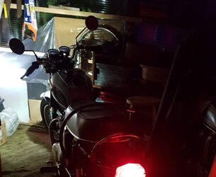
In addition to the poor standard battery-fuse connection, your photo shows your bike's wiring is not standard, it has been mangled, possibly because it was damaged by a short, certainly to match the battery, which is obviously a replacement but not fitted correctly ...
As I have written above, your bike's electrics are "positive ground" - the battery positive terminal is connected to the metal parts of the bike.
However, the replacement battery has been fitted with the "
not ground" negative terminal very close to the positive-grounded frame tube ...

Triumph always fitted original Lucas batteries with the "not ground" negative terminal nearest the oil tank, which was fully rubber-mounted also from 66.
Like
@grandpaul, I am curious how the pictured ground works - the oil tank is rubber-mounted, the "straps" connecting the oil tank to the other side of the frame and suspending the battery/carrier are also rubber-mounted on the other side of the frame ...

Imho nevertheless plan to correct the highlighted issues; also: the fuse holder is not original, tape covered wiring (both ends of the fuse holder) always makes me wonder what bodges it is hiding ...

You should run that solid ground wire from the battery to the same point on the top of the cylinder head that the wiring harness is grounded to.
Basically yes, but not that particular wire:-
. If you intend to continue using the pictured battery, turn it around in the carrier so the -ve terminal is closest to the oil tank.
. The new Red wire between the battery +ve terminal and (practically) one of the studs that connects a frame-engine head steady to a rocker box should be
"14 gauge" (14AWG) size (all original 71 onwards wiring is similar to 18AWG, too low rated for wires that are common to several circuits - the wire connected to either battery terminal ...).
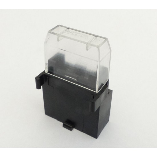
. The wire between the battery +ve terminal and the head steady stud should include the main fuse/holder close to the battery terminal. Search online for "clip together blade fuse holder"; ideally you will find similar to:-
... ("clip together" so you can clip on a second holder for a spare fuse?

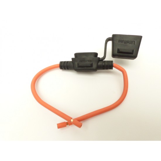
) but you might have to settle for:-
... just ensure the wire is 14AWG size.
. The reason I suggest a blade fuse holder is the fuses are much more widely available than original type cylindrical fuses. Fit a 15A fuse.
. Main/only fuse in the only wire connected to the battery +ve terminal, the fuse holder connected to battery -ve can be discarded; insulating tape stripped off the wire, I can advise where the necessary new
14AWG Brown/Blue wire from the battery -ve terminal should be connected?
The links above to 14AWG size wire are to
British Wiring; afaik, they are the only US supplier of wires matching standard Lucas insulation colours, matching bullet terminals and connectors, standard spade terminals and matching insulators.


 At best, stainless cap only?
") Over the spindle would help to avoid problems refitting the gearbox outer cover over the spindle.
Over the spindle would help to avoid problems refitting the gearbox outer cover over the spindle. AREA IS THE ONLY OIL LEFT IN THE BIKE.